Sunday 7 October 2012
More Parrot 2.0
I haven't been doing anything with electronics recently but I have been flying my Parrot 2.0 drone. Here are some videos:
Tuesday 26 June 2012
Quadrocopters
I have recently upgraded my Parrot AR Drone to the new 2.0 version. The new version features a number of upgrades but there are two in particular which are really standing out so far.
The front facing camera has been upgraded to 720P HD quality. This is much better than the first Parrot drone which had a camera which really wasn't great. Unfortunately the new camera uses a rolling shutter which means that at times the video can be quite wobbly but mostly the video quality is good enough to still be impressive.
The other big upgrade in the 2.0 is the addition of an "Absolute Control" mode where control is done relative to the pilot rather than relative to the drone. For example, this means that when you tilt your iPad towards you the drone will move towards you rather than simply moving backwards. This makes flying the drone much easier!
Here are a couple of videos from some flights which I did today.
The Parrot 2.0 delivers impressive performance for a relatively low price tag. However, it is interesting to see what can be achieved if you have a (much) higher budget. The OktoKopter-XL costs >£5K-£10K for the drone + camera + other necessary parts and can produce some really impressive videos such as the following.
MikroKopter - Zoom from Holger Buss on Vimeo.
MikroKopter - Wind turbine from Holger Buss on Vimeo.
Monday 25 June 2012
Exciting Components
I haven't been spending much time on electronics recently but I have been seeing some really interesting components.
HackHD (http://hackhd.com/)
I think this is a very recent project but I can't see any dates on the HackHD site. This simple PCB features a 1080P 30FPS camera which can be controlled electronically and records to an SD card. The website is very bare with some details about the PCB but no example videos. Thankfully there are some good examples and comparisons on Youtube.
The site offers to sell you a starter kit including PCB, battery, memory card and some other components for US $140 (about £90) which seems pretty reasonable.
808 Car Key Micro Camera (http://chucklohr.com/808/)
While Googling for reviews of the HackHD I came across a thread on a paintballing forum which was discussing the HackHD. One poster in this thread suggested that they would prefer to use an 808 Camera which supposedly only costs USD $38 for 720P video. A bit more Googling turned up the link above which describes the 808 camera as a line of cheap HD cameras out of China. The most recent edition is the #18 model which supports 720P 30FPS video and is available for around USD $36 on ebay.
The same ebay sellers are offering a cheap 1080P video camera but this thread suggests that the video capture is unreliable.
Electric Imp (http://www.electricimp.com/)
Electric Imp is a micro controller with a wifi connection in a standard SD card form factor.

The card will retail for USD $25 and there are several interesting development kits which cost between USD $7 and $25. This is a very recent project so the products haven't actually been released yet but are due very soon.
I'm particularly interested in this as it is impressively cheap for a wifi solution.
Thursday 31 May 2012
Raspberry Pi Kernel Image
At the end of my last post I needed a Debian Linux Image package. I posted on the forums but didn't get anywhere. A bit of googling turned up a couple of useful pages which talked about how to build a Debian Linux image package. Based on these pages I ran the following commands.
cd /lib/modules/3.1.9+/build
time make-kpkg kernel_imageThis ended with an error:
arm-Linux-gnueabi-ld: not foundI ran the following command and spotted that there were some existing symlinks for other gnueabi tools:
ls -l /usr/bin/arm-linux-gnueabi*I therefore tried adding a symlink for ld. A couple of hours later the build failed and in the end (after several more multi hour builds) I needed all of these links:
sudo ln -s /usr/bin/ld /usr/bin/arm-linux-gnueabi-ld
sudo ln -s /usr/bin/ar /usr/bin/arm-linux-gnueabi-ar
sudo ln -s /usr/bin/nm /usr/bin/arm-linux-gnueabi-nm
sudo ln -s /usr/bin/objcopy /usr/bin/arm-linux-gnueabi-objcopy
sudo ln -s /usr/bin/objdump /usr/bin/arm-linux-gnueabi-objdump
sudo ln -s /usr/bin/strip /usr/bin/arm-linux-gnueabi-stripWith these links in place I cleaned the build point and rebuilt the kernel.
time fakeroot make-kpkg clean
gzip -dc /proc/config.gz > .config
time fakeroot make-kpkg kernel_imageSadly after 6 hours of building the Debian package failed to be created due to permissions issues. Cue restarting with sudo.
time sudo fakeroot make-kpkg clean
gzip -dc /proc/config.gz > .config
time sudo fakeroot make-kpkg kernel_imageAttempting to install the resulting Debian package prompted a warning that I already had a kernel in /lib/modules/3.1.9+. I moved the existing kernel out of the way and installed the new kernel package. I then copied the kernel headers back into place.
sudo mv /lib/modules/3.1.9+ /lib/modules/3.1.9+.old
sudo dpkg -i linux-image-3.1.9+_3.1.9+-10.00.Custom_armel.deb
sudo cp -r /lib/modules/3.1.9+.old/build /lib/modules/3.1.9+/buildWith all of this in place I could finally try again to build and install my ar5523 module.
cd ~/ar5523
sudo m-a a-i ar5523
sudo cp ../uath-ar5523.bin /usr/local/lib/firmware/
sudo modprobe ar5523
sudo shutdown -r nowAfter all this I plugged in my WG111T and sadly it didn't work! The following errors show up in dmesg while the WG111T is plugged in:
usb 1-1.3.4: new high speed USB device number 49 using dwc_otg
usb 1-1.3.4: New USB device found, idVendor=1385, idProduct=4250
usb 1-1.3.4: New USB device strings: Mfr=1, Product=2, SerialNumber=3
usb 1-1.3.4: Product: WG111T
usb 1-1.3.4: Manufacturer: Atheros Communications Inc
usb 1-1.3.4: SerialNumber: 1.0
usb 1-1.3.4: MAC/BBP AR5523, RF AR2112
ieee80211 phy0: Selected rate control algorithm 'minstrel_ht'
DEBUG:handle_hc_chhltd_intr_dma:: XactErr without NYET/NAK/ACK

DEBUG:handle_hc_chhltd_intr_dma:: XactErr without NYET/NAK/ACK

DEBUG:handle_hc_chhltd_intr_dma:: XactErr without NYET/NAK/ACK

usb 1-1.3.4: timeout waiting for command reply
usb 1-1.3.4: could not send read command 07h
DEBUG:handle_hc_chhltd_intr_dma:: XactErr without NYET/NAK/ACK

DEBUG:handle_hc_chhltd_intr_dma:: XactErr without NYET/NAK/ACK

DEBUG:handle_hc_chhltd_intr_dma:: XactErr without NYET/NAK/ACK

usb 1-1.3.4: timeout waiting for command reply
usb 1-1.3.4: could not send read command 07h
DEBUG:handle_hc_chhltd_intr_dma:: XactErr without NYET/NAK/ACK

DEBUG:handle_hc_chhltd_intr_dma:: XactErr without NYET/NAK/ACK

usb 1-1.3.4: timeout waiting for command reply
usb 1-1.3.4: could not send read command 07h
DEBUG:handle_hc_chhltd_intr_dma:: XactErr with NYET/NAK/ACK

DEBUG:handle_hc_chhltd_intr_dma:: XactErr without NYET/NAK/ACK

DEBUG:handle_hc_chhltd_intr_dma:: XactErr without NYET/NAK/ACK

DEBUG:handle_hc_chhltd_intr_dma:: XactErr without NYET/NAK/ACK

DEBUG:handle_hc_chhltd_intr_dma:: XactErr without NYET/NAK/ACK

DEBUG:handle_hc_chhltd_intr_dma:: XactErr without NYET/NAK/ACK

DEBUG:handle_hc_chhltd_intr_dma:: XactErr without NYET/NAK/ACK

DEBUG:handle_hc_chhltd_intr_dma:: XactErr without NYET/NAK/ACK

DEBUG:handle_hc_chhltd_intr_dma:: XactErr without NYET/NAK/ACK

DEBUG:handle_hc_chhltd_intr_dma:: XactErr without NYET/NAK/ACK

DEBUG:handle_hc_chhltd_intr_dma:: XactErr without NYET/NAK/ACK

DEBUG:handle_hc_chhltd_intr_dma:: XactErr without NYET/NAK/ACK

DEBUG:handle_hc_chhltd_intr_dma:: XactErr without NYET/NAK/ACK
Thursday 17 May 2012
Patching the ar5523 driver
I made further progress with building a driver for my WG111T USB wifi. This is the latest incantation that I am using:
svn co svn://svn.berlios.de/fullstory/ar5523/trunk ar5523
wget http://verein.lst.de/~hch/ar5523.tgz
tar -xf ar5523.tgz ar5523/uath-ar5523.bin --strip 1
cd ar5523
QUILT_PATCHES="debian/patches" quilt delete kcompat-2.6.34
QUILT_PATCHES="debian/patches" quilt new usbfix
QUILT_PATCHES="debian/patches" quilt add ar5523.c
... edit ar5523.c as per the diff below ...
QUILT_PATCHES="debian/patches" quilt refresh
dpkg-buildpackage -us -uc
sudo dpkg -i ../ar5523-source*deb
sudo m-a a-i ar5523
Here are the diffs of the fixes which I had to make. A couple of USB functions have changed name and a networking structure has changed a bit:
Index: ar5523/ar5523.c
===================================================================
--- ar5523.orig/ar5523.c 2012-05-17 22:59:30.741403331 +0100
+++ ar5523/ar5523.c 2012-05-17 23:01:02.500427071 +0100
@@ -886,7 +886,7 @@
}
static int ar5523_add_interface(struct ieee80211_hw *hw,
- struct ieee80211_if_init_conf *conf)
+ struct ieee80211_vif *conf)
{
struct ar5523 *ar = hw->priv;
@@ -1122,7 +1122,7 @@
struct ar5523_tx_cmd *cmd = &ar->tx_cmd[i];
usb_kill_urb(cmd->urb);
- usb_buffer_free(ar->dev, AR5523_MAX_TXCMDSZ,
+ usb_free_coherent(ar->dev, AR5523_MAX_TXCMDSZ,
cmd->buf, cmd->urb->transfer_dma);
usb_free_urb(cmd->urb);
}
@@ -1142,7 +1142,7 @@
ar5523_err(ar, "could not allocate tx urb");
goto out;
}
- cmd->buf = usb_buffer_alloc(ar->dev, AR5523_MAX_TXCMDSZ,
+ cmd->buf = usb_alloc_coherent(ar->dev, AR5523_MAX_TXCMDSZ,
GFP_KERNEL,
&cmd->urb->transfer_dma);
if (!cmd->buf) {
@@ -1159,7 +1159,7 @@
while (--i >= 0) {
struct ar5523_tx_cmd *cmd = &ar->tx_cmd[i];
- usb_buffer_free(ar->dev, AR5523_MAX_TXCMDSZ,
+ usb_free_coherent(ar->dev, AR5523_MAX_TXCMDSZ,
cmd->buf, cmd->urb->transfer_dma);
usb_free_urb(cmd->urb);
}
@@ -1175,7 +1175,7 @@
struct ar5523_rx_cmd *cmd = &ar->rx_cmd[i];
usb_kill_urb(cmd->urb);
- usb_buffer_free(ar->dev, AR5523_MAX_RXCMDSZ,
+ usb_free_coherent(ar->dev, AR5523_MAX_RXCMDSZ,
cmd->buf, cmd->urb->transfer_dma);
usb_free_urb(cmd->urb);
}
@@ -1195,7 +1195,7 @@
ar5523_err(ar, "could not allocate rx urb");
goto out;
}
- cmd->buf = usb_buffer_alloc(ar->dev, AR5523_MAX_TXCMDSZ,
+ cmd->buf = usb_alloc_coherent(ar->dev, AR5523_MAX_TXCMDSZ,
GFP_KERNEL,
&cmd->urb->transfer_dma);
if (!cmd->buf) {
@@ -1213,7 +1213,7 @@
if (error) {
ar5523_err(ar, "error %d when submitting rx urb",
error);
- usb_buffer_free(ar->dev, AR5523_MAX_RXCMDSZ,
+ usb_free_coherent(ar->dev, AR5523_MAX_RXCMDSZ,
cmd->buf, cmd->urb->transfer_dma);
usb_free_urb(cmd->urb);
return error;
@@ -1228,7 +1228,7 @@
usb_kill_urb(cmd->urb);
- usb_buffer_free(ar->dev, AR5523_MAX_RXCMDSZ,
+ usb_free_coherent(ar->dev, AR5523_MAX_RXCMDSZ,
cmd->buf, cmd->urb->transfer_dma);
usb_free_urb(cmd->urb);
}
With this patch in place I can now build the ar5523 module but I can't install it because of the following error:
Done!
unpack
Extracting the package tarball, /usr/src/ar5523.tar.bz2, please wait...
"/usr/share/modass/packages/default.sh" build KVERS=3.1.9+ KSRC=/usr/src/linux-OLDVERSION.1337203974 kdist_image
Done with /lib/modules/3.1.9+/ar5523-modules-3.1.9+_0~slh.12_armel.deb .
dpkg -Ei /lib/modules/3.1.9+/ar5523-modules-3.1.9+_0~slh.12_armel.deb
Selecting previously deselected package ar5523-modules-3.1.9+.
(Reading database ... 48573 files and directories currently installed.)
Unpacking ar5523-modules-3.1.9+ (from .../ar5523-modules-3.1.9+_0~slh.12_armel.deb) ...
dpkg: dependency problems prevent configuration of ar5523-modules-3.1.9+:
ar5523-modules-3.1.9+ depends on linux-image-3.1.9+; however:
Package linux-image-3.1.9+ is not installed.
dpkg: error processing ar5523-modules-3.1.9+ (--install):
dependency problems - leaving unconfigured
Errors were encountered while processing:
ar5523-modules-3.1.9+
I: Direct installation failed, trying to post-install the dependencies
apt-get -f install
Reading package lists... Done
Building dependency tree
Reading state information... Done
Correcting dependencies... Done
The following packages will be REMOVED:
ar5523-modules-3.1.9+
0 upgraded, 0 newly installed, 1 to remove and 29 not upgraded.
1 not fully installed or removed.
After this operation, 81.9 kB disk space will be freed.
Do you want to continue [Y/n]? y
(Reading database ... 48579 files and directories currently installed.)
Removing ar5523-modules-3.1.9+ ...
Clearly the next challenge is to get a linux-image-3.1.9+ package installed.
Wednesday 16 May 2012
Raspberry Pi Progress
In my last post I had issues with getting the kernel headers installed. I took another look today and spotted that there were suspiciously few items in the github clone on my SD card. It turned out that my SD card was full!

When creating the SD card I failed to spot the optional step to resize the root partition. I wasn't entirely convinced by the steps on the wiki as it talks about deleting the swap partition and doesn't appear to recreate it. After a bit of browsing I used the following process.
Next I moved the swap partition to the end of the SD card:
Launch gparted from within the GUI (under the Preferences menu), select the swap partition, Partition -> Resize/Move. It is possible to just drag the swap partition to the end of the SD card and apply the changes. After a system reboot there is plenty of empty space beyond the end of the root partition.
Now I can resize the root partition using the instructions in the wiki:
Here is my fdisk output before I made any changes:

sudo fdisk -cu /dev/mmcblk0
sudo shutdown -r now
After the reboot you need to resize the actual partition. The resize2fs will resize your main partition to the new size from the changed partition table.
sudo resize2fs /dev/mmcblk0p2
Done! Here is my fdisk output after I made these changes:


However this still failed a little further on with a different error message.


When creating the SD card I failed to spot the optional step to resize the root partition. I wasn't entirely convinced by the steps on the wiki as it talks about deleting the swap partition and doesn't appear to recreate it. After a bit of browsing I used the following process.
Resizing the root partition
Firstly, to be able to run gparted (next step) you need to set the root password:
sudo passwd root
Next I moved the swap partition to the end of the SD card:
Launch gparted from within the GUI (under the Preferences menu), select the swap partition, Partition -> Resize/Move. It is possible to just drag the swap partition to the end of the SD card and apply the changes. After a system reboot there is plenty of empty space beyond the end of the root partition.
Now I can resize the root partition using the instructions in the wiki:
Here is my fdisk output before I made any changes:

sudo fdisk -cu /dev/mmcblk0
- p to see the current start of the main partition
- d, 2 to delete the main partition
- n, p, 2 to create a new primary partition
- w write the new partition table
sudo shutdown -r now
After the reboot you need to resize the actual partition. The resize2fs will resize your main partition to the new size from the changed partition table.
sudo resize2fs /dev/mmcblk0p2
Done! Here is my fdisk output after I made these changes:

Building Kernel Headers
With plenty of disk space available I was able to follow the instructions in my last post to build the kernel headers.sudo apt-get install git git clone --depth 1 https://github.com/raspberrypi/linux.git sudo mv linux /lib/modules/3.1.9+/build cd /lib/modules/3.1.9+/build make mrproper gzip -dc /proc/config.gz > .config make modules_prepare
Building ar5523 driver
With the kernel headers in place I as able to get further with the driver build.
However this still failed a little further on with a different error message.

make[3]: Entering directory `/lib/modules/3.1.9+/build'

  WARNING: Symbol version dump /lib/modules/3.1.9+/build/Module.symvers
           is missing; modules will have no dependencies and modversions.

  CC [M]  /usr/src/modules/ar5523/ar5523.o
/usr/src/modules/ar5523/ar5523.c:873: warning: ‘struct ieee80211_if_init_conf’ declared inside parameter list
/usr/src/modules/ar5523/ar5523.c:873: warning: its scope is only this definition or declaration, which is probably not what you want
/usr/src/modules/ar5523/ar5523.c: In function ‘ar5523_add_interface’:
/usr/src/modules/ar5523/ar5523.c:885: error: dereferencing pointer to incomplete type
/usr/src/modules/ar5523/ar5523.c:888: error: dereferencing pointer to incomplete type
/usr/src/modules/ar5523/ar5523.c: At top level:
/usr/src/modules/ar5523/ar5523.c:898: warning: ‘struct ieee80211_if_init_conf’ declared inside parameter list
/usr/src/modules/ar5523/ar5523.c:1035: warning: initialization from incompatible pointer type
/usr/src/modules/ar5523/ar5523.c:1037: warning: initialization from incompatible pointer type
/usr/src/modules/ar5523/ar5523.c:1038: warning: initialization from incompatible pointer type
/usr/src/modules/ar5523/ar5523.c: In function ‘ar5523_free_tx_cmds’:
/usr/src/modules/ar5523/ar5523.c:1120: error: implicit declaration of function ‘usb_buffer_free’
/usr/src/modules/ar5523/ar5523.c: In function ‘ar5523_alloc_tx_cmds’:
/usr/src/modules/ar5523/ar5523.c:1140: error: implicit declaration of function ‘usb_buffer_alloc’
/usr/src/modules/ar5523/ar5523.c:1142: warning: assignment makes pointer from integer without a cast
/usr/src/modules/ar5523/ar5523.c: In function ‘ar5523_alloc_rx_cmds’:
/usr/src/modules/ar5523/ar5523.c:1195: warning: assignment makes pointer from integer without a cast
Setting up SSH
I extracted the error message in the last step by enabling ssh so that I could use WinSCP to transfer the error log back to my Windows PC:
sudo service ssh start
Raspberry Pi Kernel Headers
As i mentiomed in my last post I have been trying to follow some instructions for building a driver for my WG111T usb wifi. I have got as far as the module assistant step which fails due to the kernel headers Debian package not being available:
I managed to find a forum thread which included some commands that sounded like they might do the right thing.
I tried to follow these instructions but only got as far as "make mrproper" before hitting an error.
I can't see how this is meant to work and I'm now a bit stuck again. The key question is how I should get the kernel headers installed.
EDIT: I have got this working in my next post.
pi@raspberrypi:~$ sudo m-a a-i ar5523
Updated infos about 1 packages
Getting source for kernel version: 3.1.9+
apt-get install kernel-headers-3.1.9+
Reading package lists... Done
Building dependency tree
Reading state information... Done
E: Unable to locate package kernel-headers-3.1.9
E: Couldn't find any package by regex 'kernel-headers-3.1.9'
apt-get install build-essential
Reading package lists... Done
Building dependency tree
Reading state information... Done
build-essential is already the newest version.
0 upgraded, 0 newly installed, 0 to remove and 29 not upgraded.
Done!
Since then I have been trying to find out how to install the kernel headers but have so far failed to get a simple answer.
I managed to find a forum thread which included some commands that sounded like they might do the right thing.
sudo apt-get install git
git clone –depth 1 https://github.com/raspberrypi/linux.git
sudo mv linux /lib/modules/3.1.9+/build
cd /lib/modules/3.1.9+/build
make mrproper
gzip -dc /proc/config.gz > .config
make modules_prepare
I tried to follow these instructions but only got as far as "make mrproper" before hitting an error.
pi@raspberrypi:/lib/modules/3.1.9+/build$ sudo make mrproper
Makefile:327: /lib/modules/3.1.9+/build/scripts/Kbuild.include: No such file or directory
/bin/bash: /lib/modules/3.1.9+/build/scripts/gcc-goto.sh: No such file or directory
make[1]: scripts/Makefile.clean: No such file or directory
make[1]: *** No rule to make target `scripts/Makefile.clean'.  Stop.
make: *** [_clean_.] Error 2
I can't see how this is meant to work and I'm now a bit stuck again. The key question is how I should get the kernel headers installed.
EDIT: I have got this working in my next post.
Wednesday 9 May 2012
Raspberry Pi Wifi - WG111T
In this post I will describe the progress I have made so far in getting my WG111T USB wifi adaptor working with Debian Linux on my Raspberry Pi.
My first stop was to consult the list of supported hardware. This was initially encouraging as it lists the WG111v2 as supported but sadly my WG111T uses a different chipset. This page also links to an example of getting an arbitrary USB wifi device working. This suggested I look for firmware on the linuxwireless.org site. Google suggested that I needed the ar5523 firmware. The change log for this firmware isn't very encouraging as it refers to the kernel panicking when the device is probed. Furthermore it's not clear how I would build and install this firmware.

My first stop was to consult the list of supported hardware. This was initially encouraging as it lists the WG111v2 as supported but sadly my WG111T uses a different chipset. This page also links to an example of getting an arbitrary USB wifi device working. This suggested I look for firmware on the linuxwireless.org site. Google suggested that I needed the ar5523 firmware. The change log for this firmware isn't very encouraging as it refers to the kernel panicking when the device is probed. Furthermore it's not clear how I would build and install this firmware.
More googling turned up a wiki page which described in much more detail about how to build and install the firmware. Following these steps I got as far as "dpkg-buildpackage -us -uc" before hitting an error that my version of debhelper was too old. Thankfully I was able to use apt-get to force an upgrade to an appropriately newer version. This got me as far as running "m-a a-i ar5523" where I hit the following error:

Without the kernel headers I am now stuck so my next task is to work out how to get these installed. It was late by this point so I gave up for the night.
Getting Started with Rasperry Pi
On Febuary 29th I got up at 6am along with far too many other geeks and tried to place an order for the newly released Raspberry Pi. The demand was so high for the original 10,000 units that the websites of both distributors were knocked offline. By 8:30 I managed to complete an order with Farnell from my iPhone on the way into work. Yesterday my Raspberry Pi arrived and I could finally get started!
 Like any computer the Raspberry Pi needs to be hooked up to a number of peripherals to become useful. The first and most important addition is an SD card with one of the Raspberry Pi OS images loaded onto it. I never got round to preparing this in advance so my first step was to download the Debian Squeeze image onto my windows XP netbook (my only computer with an SD card writer) and write it to my 8GB SD card (using Win32DiskImager as per these instructions).
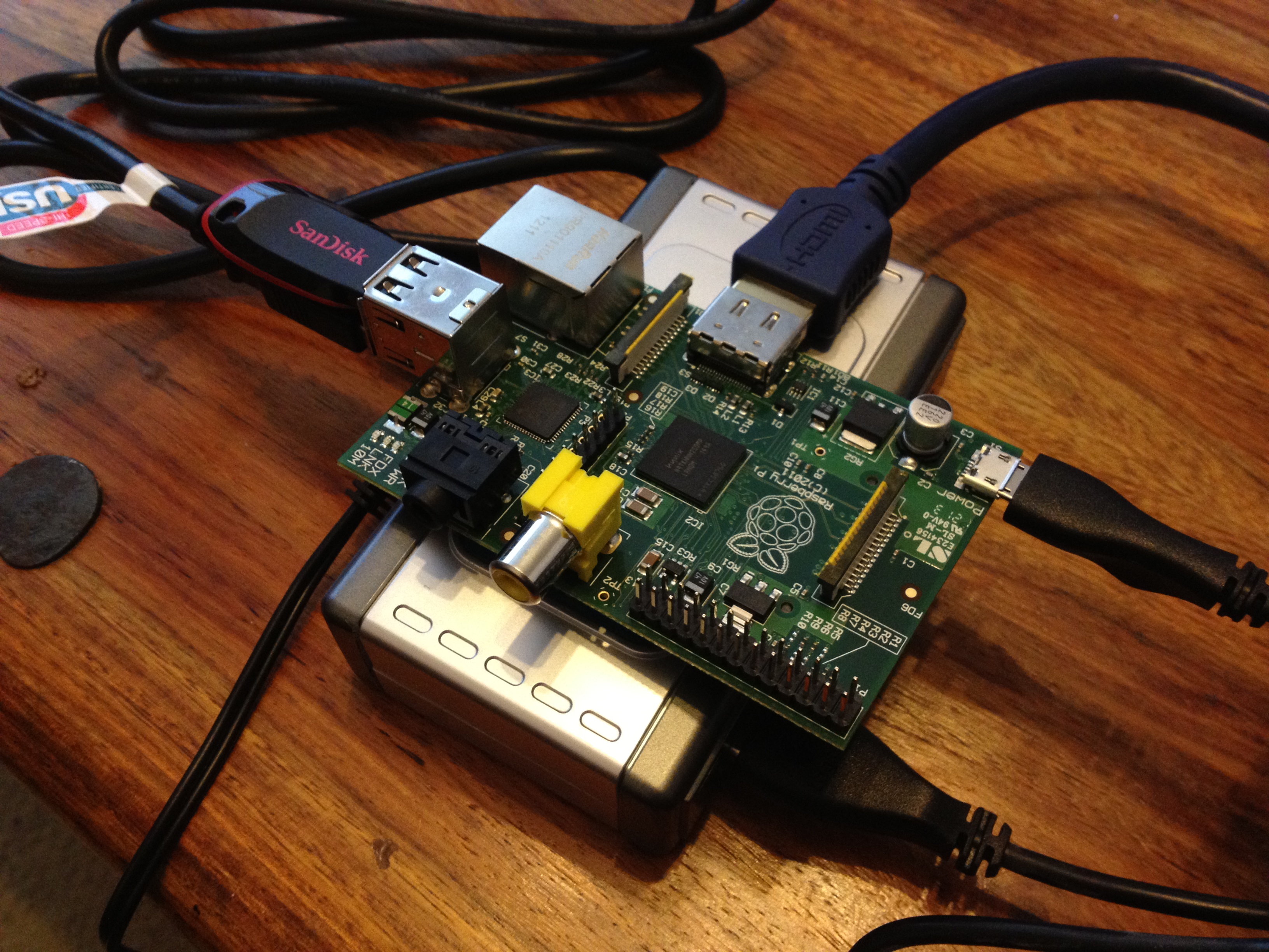
With the SD card ready I connected up my Pi.
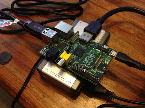 There is no power switch so as soon as I plug in the USB hub power supply the Raspberry Pi starts booting. Unfortunately the first time I did this there was no output on the screen. Thankfully this was just caused by the HDMI cable being loose in the Raspberry Pi - the connector is quite stiff and I had to push firmly to fully insert my cable. The screen didn't actually display anything with a properly inserted connector but a quick reboot of the Pi was enough to prompt the connection to be detected.
After all this I was rewarded with a login prompt requiring me to head back to the OS downloads page to check the default username and password. Once logged in I set the clock at the suggestion of the welcome message and then considered my next move.
I ultimately want to connect my Pi over wifi and I have an old WG111T USB wifi radio lying around. My first real challenge is to get this USB wifi working. While I work on this I dug out a huge network cable to stretch across my room to my router and hooked up my Pi. Amazingly, after a few seconds the Pi had successfully DHCP'd and I could ping www.google.com. At this point I decided to make my Pi experience a bit prettier and ran startx to launch the GUI.
 I had a quick play with the browser and found that things seemed sluggish but usable. An impressive feat for such a cheap device! I was also amused by the -1% CPU being used by some processes :)


With the SD card ready I connected up my Pi.
- 4 port powered USB hub - this expands the 2 built in USB ports to 5 USB ports. However, I'm using one of the hub ports plus a micro USB cable to power the Pi which only leaves me with 4 ports available.
- 16GB USB memory stick for extra storage.
- Combined USB keyboard/mouse wireless receiver.
- HDMI cable from the Pi to my projector which I will use as the screen.
After all this I was rewarded with a login prompt requiring me to head back to the OS downloads page to check the default username and password. Once logged in I set the clock at the suggestion of the welcome message and then considered my next move.
I ultimately want to connect my Pi over wifi and I have an old WG111T USB wifi radio lying around. My first real challenge is to get this USB wifi working. While I work on this I dug out a huge network cable to stretch across my room to my router and hooked up my Pi. Amazingly, after a few seconds the Pi had successfully DHCP'd and I could ping www.google.com. At this point I decided to make my Pi experience a bit prettier and ran startx to launch the GUI.


Before I got my Pi I had been encouraged about the possibility of getting my USB wifi working thanks to the list of verified hardware which included the WG111. Unfortunately the verified version was the WG111v2 not the WG111T so I am in fact stepping into uncharted territory. My next post will detail my progress with this task.
Wednesday 2 May 2012
Little Bits
I have recently started watching some TED talks again on my way to work. Yesterday I saw an excellent presentation about a project called Little Bits.

 Little Bits is an attempt to do to electronics what Lego did to construction - make it fun and accessible for kids to play with. It's worth checking out the TED talk.

Sunday 22 April 2012
Electronics to keep the wife happy
This weekend I decided to do something a bit more obviously useful than my usual projects. My house includes a cupboard under the stairs that is lit by a battery powered light. However, the light is a bit useless as it is always running out of battery really quickly.


The first step is to open up the light and take a look inside. This turned out to be quite straightforward as I just needed to remove four screws and pull the top off.
The internals are very simple with color coded wires. The only surprise is that there was a round female connector fitted to a round hole on the rim of the light. This looks like it would allow the light to be mains powered but that is no good to me as there are no sockets in the cupboard I'm using the light in.
With the cover off I took the chance to measure the current used when the light is switched on. The result: 500mA! No wonder the batteries lasted for such a short time! However, I'm not entirely surprised by this result as the light was using an incandescent bulb.
As an aside - I always find measuring current really awkward as you have to insert the multimeter in series in the circuit which is tricky when the probes are just pointy metal tips rather than clips which can hold a wire.
The next step is to make this light better. I decided the easiest way to do this would be to replace the incandescent bulb with an LED. I took a look on maplin and picked out a bright white LED which runs at 3.6V and only draws 100mA to produce 18000mcd of light. According to this site 18000mcd is 2.1 lumens which compares to 850 lumens for a 60w incandescent light bulb.
The 3.6V requirement means that I only need three of my 1.2V rechargeable batteries and won't need to add a resistor. The first step was to insert a wire instead of the fourth battery.
The next step was to remove the incandescent bulb along with its screw socket (which I have saved in case I ever need them in another project) and solder an LED in its place. The only tricky part of this was that the wires in the light were stranded instead of solid core which made the soldering more fiddly.
That's all there was to it. I put the case back together, turned on the light and took a picture.
The light is brighter than this picture suggests (my phone overcompensated with the exposure) but it is a bit less bright than I had been hoping. In future I might add an extra LED or two which would double or triple the light output with a corresponding reduction in battery life (more LEDs = more current but the same voltage).
Once everything was assembled I got out my multimeter and measured the current and was pleasantly surprised to find the current was only 70mA rather than the expected 100mA. Since I am using 1700mA batteries this means I expect a battery life of about 24 hours compared to the 3 hours which I would have got with the incandescent bulb.
Wednesday 18 April 2012
Wiimote Head Tracking - Follow Up
After my previous post I came across some interesting related content.
More Head Tracking
I found a tutorial which used a different Wii library (Wii Yourself) and describes how to create a clone of the Johnny Lee VR demo using Ogre3D.
Light Brush

I also decided to take a look at r/arduino and quickly spotted an interesting related project which uses the Wiimote as part of an Arduino powered Light Brush. The reddit thread credits this blog (http://liightbrush.wordpress.com/) with the idea and links to this blog (http://mrarduino.blogspot.co.uk/) about the implementation referenced in the reddit post.
A bit of further googling turned up http://kenfrederick.blogspot.co.uk/2009/08/lightbrush.html which was an interesting post about trying to implement a light brush. This post also links to some other similar projects such as the Lightscythe.
Monday 16 April 2012
Wiimote Head Tracking
Background
In December 2006 the Nintendo Wii was released. This included the Wiimote controller which provided an interesting new motion tracking system. The Wiimote connects to the Wii over Bluetooth and includes two kinds of sensors. A 3-axis accelerometer and an IR camera. For the purposes of this post the camera is the more interesting part.The infrared camera has a resolution of 1024x768 with built-in hardware blob tracking of up to 4 points at 100Hz. This is used in combination with the Wii sensor bar which is actually just an array of 6 IR LEDs, 3 at each end, to provide accurate motion tracking of the Wiimote when it is pointed at the sensor bar.
In December 2007 a develope called Johnny Chung Lee posted a video showing how the Wiimote could actually be used in reverse to accurately track a users head. This involved mounting IR LEDs on some glasses to take the place of the sensor bar and placing the Wiimote in front of the screen pointing at the user.
This demo was built on top of the Wiimotelib C# library for using the Wiimote on windows. A forum which discusses the head tracking demo is available here.
In a recent episode of Gadget Geeks on Sky One they used this technology to build a virtual window for a hotel room. This inspired me to investigate the technology myself.
My Hardware and Results
To build my own IR glasses I bought the following components:- 400mAh Lithium polymer battery
- Lithium polymer mini USB charger
- 950nm IR LEDs
- 15ohm resistor
- SPDT Switch
The complete glasses:

Close up on the side with the switch and the battery.

Full view of the side with the battery.

I then setup a Wiimote on top of my TV with some masking tape holding it in place. I used some more masking tape to hold an iPhone wide angle legs in front of the camera to give it a wider field of view - the camera normally only has a ~45 degree field of view.
A view of the TV including the attached Wiimote:

A close up of the Wiimote:

The results can be seen in this video.
Conclusions
I was quite pleased with how good this looked. However, the are a few key limitations.
- The lack of stereoscopic depth cues means that in person the 3D effect is much less effective than the video would suggest. If I combined this head tracking with a 3D TV I expect the combined effect would be really impressive.
- The field of view of the Wiimote camera is a really limiting factor as it is easy to move out of its view at which point obviously the head tracking stops working.
- The previous limitation is made much worse by the fact that the camera only works over fairly short distances. I found that once I moved much more than a meter away from the camera it started to struggle to keep track of me. This forces you to stay much closer where the narrow field of view is more annoying.
Other Consoles
The Wii has sold the highest number of units out of the current generation of games consoles (vs the Xbox 360 and PS3). However, as of Autumn 2010, both of the rival consoles have released their own motion tracking systems. Interestingly, both of these systems work in a similar way to the camera based head tracking covered in this post. In fact, the original creator of the head tracking demo, Johnny Chung Lee, ended up working on the Xbox Kinect development team.Xbox Kinect
The Xbox Kinect system uses an infrared projector to project a pattern of infrared light. This is then captured by a 640x480 pixel 30fps infrared camera. This input is augmented with a 640x480 pixel 30fps rgb camera. The advantage of this approach is that the IR light source and detector can be contained in the same package and the player doesn't need to wear/hold anything to be tracked.
It is interesting to note that both the resolution and frame rate of the IR camera is lower than the one used in the Wiimote.
Playstation Move
The Playstation Move uses an approach which is much closer to the one described in this post. The Playstation Eye camera provides a 640x480 60fps rgb picture which works even in very low light. This enables the use of the Playstation Move controllers which have a coloured sphere on the end. The system automatically picks the best color to stand out against the current background and then uses simple image processing to track the coloured sphere within the camera image. The known size of the sphere allows for the accurate measurement of depth.
Once again the actual resolution of the camera being used is lower than the one used in the Wiimote.
Research
Johnny Chung Lee has a blog which has some interesting posts about motion tracking and other tech topics. The post which stood out to me was this one. In particular, the following two videos are pretty exciting. Both of these are systems that work entirely by analysing RGB video without any extra sensor data.Monday 9 April 2012
New Blog - Coding
I haven't been doing much work on Arduino projects recently as I have been spending all of my time on coding projects. I have enjoyed posting to this blog so I have started a new blog to talk about these coding projects.
http://mchr3k-coding.blogspot.com/2012/04/introduction.html
Friday 30 March 2012
Wireless sensor node - software (15)
My home wireless sensor network has now been operational for just over a
week. It currently only consists of two nodes.
A base station.


A base station.

A
single wireless RF sensor.

In
my last post I was concentrating on getting the base station
constructed and deployed. Since then I have been focusing on enhancing
the software which runs on the base station and the software which I am
currently running on my own PC to download the temperature readings.
The
base station exposes a command driven interface over Bluetooth. The
long term plan is to use a raspberry pi to download readings in real
time. However, in the mean time I have programmed the base station to
write readings to file every hour. These files are read over the base
station command interface by my desktop application.
The Bluetooth interface currently accepts all of the following commands (along with some other debug related commands):

My intention is to upload these readings to https://pachube.com/ but I haven't got round to writing the code to do this yet.
The full code for my windows application is available here.
- set_time_<n> - this allows the real time to be set on the base station. No readings are recorded until this has been set.
- ls - List the files in the root of the SD card.
- cat <file> - Return the contents of a file.
- rm <file> - Delete a file.
- rm * - Delete all the files.

My intention is to upload these readings to https://pachube.com/ but I haven't got round to writing the code to do this yet.
The full code for my windows application is available here.
Monday 19 March 2012
Wireless sensor node - enclosure mark 2 (follow up) (14)
At the end of my last post I had packed all of the components of my base station into an enclosure and had everyone working. Almost.
The one issue I found was that whenever I was connected to the base station over Bluetooth, the base station was unable to receive temperature readings over the 315MHz RF link.
This is what the setup looked like when it didn't work.

In the end I posted to the Arduino forums and spoke to some friends about the issue and concluded that the Bluetooth RF must be interfering with the actual circuitry of the 315MHz RF receiver. My first idea was to try and setup some kind of electromagnetic shielding around the 315MHz RF receiver module. However, before I began working on this I decided to try simply moving the Bluetooth module further away from the 315MHz RX module.
And now it works! The extra ~5cm of distance is enough to avoid whatever interference was previously taking place.
The one issue I found was that whenever I was connected to the base station over Bluetooth, the base station was unable to receive temperature readings over the 315MHz RF link.
This is what the setup looked like when it didn't work.

In the end I posted to the Arduino forums and spoke to some friends about the issue and concluded that the Bluetooth RF must be interfering with the actual circuitry of the 315MHz RF receiver. My first idea was to try and setup some kind of electromagnetic shielding around the 315MHz RF receiver module. However, before I began working on this I decided to try simply moving the Bluetooth module further away from the 315MHz RX module.
Sunday 18 March 2012
Wireless sensor node - enclosure mark 2 (13)
My previous attempt to pack all the parts of my base station into an enclosure ended in failure. I previously attempted to find an alternative box on the Hobbycraft website but was underwhelmed by the 6 search results in their online store. I was therefore not expecting much when I went to my local Hobbycraft store this weekend.


I was actually really impressed! Hobbycraft had 2 entire rows of boxes of various sizes and colors! I bought three sizes - a medium one for storage, a smaller one to hold my base station parts and the smallest one to potentially hold a wireless sensor node. It turns out that my previous search results were simply the result of a poor query. I had searched for "plastic box". If I had searched for "really useful box" I would have found 100 products! The full range of really useful boxes can be seen here.
I spent some time re-arranging my breadboards and wiring and produced the following circuit which fit neatly in the base station box. The components here are as follows.


To work with the base station over Bluetooth I installed a new Windows Serial client - Termite. After powering on my base station the first thing which my code requires is that I set the real time offset. This approach allows me to record a reasonably accurate time for sensor readings without needing a real time clock module. To set the time I have been using the Epoch Converter page. I use the results of this page to construct a command to send to the base station e.g. set_time_1332111967. Once this is done the base station successfully receives a reading every 5 minutes from my wireless sensor node. Yay!
Unfortunately I did hit one problem. For some reason my base station seemed unable to receive any sensor data while I was connected over Bluetooth. This surprised me as the Bluetooth frequency is 2.4GHz and I therefore don't expect it to interfere with my 315MHz transmitter on my receiver.


I was actually really impressed! Hobbycraft had 2 entire rows of boxes of various sizes and colors! I bought three sizes - a medium one for storage, a smaller one to hold my base station parts and the smallest one to potentially hold a wireless sensor node. It turns out that my previous search results were simply the result of a poor query. I had searched for "plastic box". If I had searched for "really useful box" I would have found 100 products! The full range of really useful boxes can be seen here.
I spent some time re-arranging my breadboards and wiring and produced the following circuit which fit neatly in the base station box. The components here are as follows.
- 5V 16MHz Arduino Pro Mini on the left inserted into a small breadboard.
- USB mini breakout board for power on the bottom. This is attached to the box by four screws and I cut a hole in the side of the box to allow a cable to be plugged in.
- SD card breakout board with 2GB card in middle.
- 315MHz RF receiver on the right.
- Bluesmirf silver Bluetooth module in the bottom right.


To work with the base station over Bluetooth I installed a new Windows Serial client - Termite. After powering on my base station the first thing which my code requires is that I set the real time offset. This approach allows me to record a reasonably accurate time for sensor readings without needing a real time clock module. To set the time I have been using the Epoch Converter page. I use the results of this page to construct a command to send to the base station e.g. set_time_1332111967. Once this is done the base station successfully receives a reading every 5 minutes from my wireless sensor node. Yay!
Unfortunately I did hit one problem. For some reason my base station seemed unable to receive any sensor data while I was connected over Bluetooth. This surprised me as the Bluetooth frequency is 2.4GHz and I therefore don't expect it to interfere with my 315MHz transmitter on my receiver.
Thursday 15 March 2012
Wireless sensor node - getting started with an SD card (12)
A couple of months ago I bought an SD card breakout board. The intention was that this would allow my Arduino base station to log to memory card to provide a persistent record of the sensor readings. However, apart from soldering on some male headers, I haven't done anything with the SD card breakout until now.

Serial.println(FreeRam());
The other method which I needed to use was one from pgmspace.h.
becomes
strcmp_P(stringData, PSTR("dbg_fls_f"))
The result of using PgmPrint and strcmp_P+PSTR for my sketch was the following:
As far as I can tell this has the same effect as using PgmPrint. The advantage is that F() is included in the base Arduino headers whereas PgmPrint is only available in the Sd library header. I have stuck with PgmPrint as I slightly prefer the shorter syntax.
SD vs SdFat
When I started out this article I was following the Lady Ada tutorial which pointed me at the SD library. Unfortunately I ended up hitting a bug where I could both list files and write to a file but listing files after writing to a file didn't work. This prompted me to investigate the SD library a bit further and properly understand that it was acting as a wrapper for the SdFat library.
SdFat has been updated more recently than SD and comes with a better range of examples. For both of these reasons I switched my code to use SdFat and have subsequently managed to get everything working nicely.
To prepare for writing some code to use the SD card I assembled a neat new layout on the breadboard attached to my Arduino Uno.

The next step was to write code to use the SD card. I used the Lady Ada tutorial to get started. I used the CardInfo sketch to validate that I could access the SD card and the list files sketch to demonstrate using the file system.
With this complete I set about integrating the SD card code into my wsn_arduino sketch. This seemed fairly straightforward until I tried to actually use the code at which point I started hitting mysterious crashes! :(
It turns out that the SD card library is a memory hog and I was already running low on RAM before adding the SD card code. I didn't think my existing code was using much RAM until I found out that string constants e.g. those used in Serial print statements are all stored in RAM! Argh!
Reducing Memory Used by String Constants
Firstly, it is important to be able to measure the amount of free memory so that we can see how badly/well we are doing. This can be done using the FreeMem method from SdFatUtil.h.
#include <SD.h>
...
Serial.print("Free RAM: ");
Serial.println(FreeRam());
Serial.println(FreeRam());
So what can we do to reduce this memory usage? The answer is to use the PROGMEM keyword. This instructs the compiler to store a variable in the much larger program memory space. However, using the keyword initially looks quite awkward.
The article describing its use suggests that you store strings in explicit variable and copy them into a RAM buffer before use. This is really unwieldy when you just want to print a string to the console!
The solution is to use the PSTR macro in the avr/pgmspace.h header. This has the following definition.
#define PSTR(s) ((const PROGMEM char *)(s))
This marks a string constant for storage in program memory without having to use a separate variable. However, you now need to use a different print method to access the string. Conveniently the SD card header SdFatUtils.h has just what we need in the form of PgmPrint and PgmPrintln.
#include <avr/pgmspace.h>
#include <SD.h>
#include <SD.h>
...
PgmPrint("Free RAM: ");Serial.println(FreeRam());
The other method which I needed to use was one from pgmspace.h.
strcmp(stringData, "dbg_fls_f")
becomes
strcmp_P(stringData, PSTR("dbg_fls_f"))
The result of using PgmPrint and strcmp_P+PSTR for my sketch was the following:
- Free RAM: 393 (Before)
- Free RAM: 925 (After)
- It is vital that all opened Files are closed when you are done with them as each one takes up ~68 bytes of memory while open.
- Arduino 1.0 includes support for a new F() macro which allows you to use Serial.print directly. This looks like the following.
As far as I can tell this has the same effect as using PgmPrint. The advantage is that F() is included in the base Arduino headers whereas PgmPrint is only available in the Sd library header. I have stuck with PgmPrint as I slightly prefer the shorter syntax.
SD vs SdFat
When I started out this article I was following the Lady Ada tutorial which pointed me at the SD library. Unfortunately I ended up hitting a bug where I could both list files and write to a file but listing files after writing to a file didn't work. This prompted me to investigate the SD library a bit further and properly understand that it was acting as a wrapper for the SdFat library.
SdFat has been updated more recently than SD and comes with a better range of examples. For both of these reasons I switched my code to use SdFat and have subsequently managed to get everything working nicely.
Tuesday 13 March 2012
Wireless sensor node - enclosure mark 1 (11)
I got the plastic enclosure which I ordered and had a go at fitting in
all of my base station components. Sadly the results were not ideal. It
turns out that I had been overly optimistic about the required
dimensions. The following picture shows that I was almost able to squash all of the components into the box but there was no way the lid was going to fit on properly.


I wasn't helped by the fact that the enclosure turned out to have plastic headers inside.

This reduces the available space even further as I just want to stick a breadboard onto the bottom
of the box! I was able to remove these by simply crushing/pulling them
off with pliers and sanding it down.

The main thing which I have
learnt from this is that I need more space in my base station enclosure
and I really need more breadboard space to make a neater layout. To this
end I have bought a new Arduino Pro Mini (so that I can solder male
headers onto it), a tiny breadboard to hold the Pro Mini and a new mini USB breakout (which will also get male headers for use directly on a
breadboard) board.
Sunday 4 March 2012
Wireless sensor node - enclosures (10)
I now have all of the basic hardware prepared to allow me to deploy my wireless sensor network. However, I still need to work out the best way to package the various parts.
I have ordered a couple of plastic boxes which I am planning to use to package my nodes. In particular, I want a plastic box to put my base station in so that I can screw down the usb breakout board. One of the boxes should be a perfect size to contain the base station. The smaller box will contain a wireless sensor node.
However, in the mean time I decided to try my hand at making a cheaper enclosure out of some red cardboard which I already had at home. I drew the following template using Inkscape.

The source svg file is available here. The only joint which requires glue is the tab on the left. The top and bottom are designed to be folded in on themselves without glue.
I was quite pleased with the results.
 This is now sitting on top of my kitchen cupboard broadcasting the temperature every 5 minutes. I don't have my base station setup yet but since the sensor node has an expected battery life of over a year I have plenty of time to deploy the base station!
There are two main next steps:
I have ordered a couple of plastic boxes which I am planning to use to package my nodes. In particular, I want a plastic box to put my base station in so that I can screw down the usb breakout board. One of the boxes should be a perfect size to contain the base station. The smaller box will contain a wireless sensor node.
However, in the mean time I decided to try my hand at making a cheaper enclosure out of some red cardboard which I already had at home. I drew the following template using Inkscape.

The source svg file is available here. The only joint which requires glue is the tab on the left. The top and bottom are designed to be folded in on themselves without glue.
I was quite pleased with the results.

There are two main next steps:
- Sort out the base station enclosure.
- Write more code on the base station to log a history of readings, spot when readings are missing and expose this information over the serial port.
Wednesday 29 February 2012
Wireless sensor node - prototype node (9)
It's finally time to build my first proper prototype wireless sensor node. The components are as follows:

The results without any parts in place looks like this.


Sadly having built this I found that the RF TX no longer worked reliably and the temperature sensor wasn't reporting accurate readings! This required some software fixes!
1) Fixing the RF TX
I have historically used a scheme where I sent three 16 bit values and then combined them at the receiver. However, the Manchester lib now supports sending longer messages so I've retired my pointless message combining code and simply send a single longer message.
2) Getting accurate readings out of the TMP36
The basic method for getting temp readings is as follows.
int sensorValue = analogRead(TmpPin);
// Constant: 5000 / 1024
float milliVolts = sensorValue * 4.8828125;
float tempC = (milliVolts - 500) / 10;
return tempC;
The crucial change to make when running on an ATtiny85 is to change the constant which adjusts for the reference voltage being used which in my case is certainly not 5V!
First, add the following to your setup method. This tells the ATtiny85 to use the internal 1.1V reference voltage in preference to the VCC which will change as our battery runs down.
// Select the 1.1V internal ref voltage
analogReference(INTERNAL);
Secondly, update the temp reading code as follows.
int sensorValue = analogRead(TmpPin);
// Constant: 1100 / 1024
float milliVolts = sensorValue * 1.07421875;
float tempC = (milliVolts - 500) / 10;
return tempC;
3) Getting more accurate readings out of the TMP36
The ATtiny85 internal 1.1V reference voltage isn't very accurate so it's worth calibrating the constant you are using. To do this I took a temperature reading from the TMP36 when connected to my ATtiny85 and when connected to an Arduino Uno. I then used the following formula:
V_calib = V_base * ((T_ref + 50) / (T_base + 50))
V_base = 1100
T_ref = temp as measured on Arduino Uno
T_base = temp as measured on ATtiny85
I ended up with V_calib = 1028 which gave me fairly accurate temp readings.
A working wireless sensor node! (I have added a ~20cm antenna wire since the previous pictures)


I have tested this node briefly but I won't deploy it until I do some more work.
For the wireless sensor node I want to build an enclosure.
For the base station I want to build an enclosure and write code to handle storing readings and allowing download over bluetooth.
As ever, the Arduino code is available on Github:
- CR2032 3V battery + battery holder
- ATtiny85 MCU + 8 pin socket
- TMP36 temperature sensor + 3 pin female header
- 315MHz RF TX module + 4 pin female header
- A small amount of tripad board

The results without any parts in place looks like this.

And this is what it looks like with all the parts in place.

I'm fairly pleased with how neat the soldering turned out.

Sadly having built this I found that the RF TX no longer worked reliably and the temperature sensor wasn't reporting accurate readings! This required some software fixes!
1) Fixing the RF TX
I have historically used a scheme where I sent three 16 bit values and then combined them at the receiver. However, the Manchester lib now supports sending longer messages so I've retired my pointless message combining code and simply send a single longer message.
2) Getting accurate readings out of the TMP36
The basic method for getting temp readings is as follows.
// Constant: 5000 / 1024
float milliVolts = sensorValue * 4.8828125;
float tempC = (milliVolts - 500) / 10;
return tempC;
The crucial change to make when running on an ATtiny85 is to change the constant which adjusts for the reference voltage being used which in my case is certainly not 5V!
First, add the following to your setup method. This tells the ATtiny85 to use the internal 1.1V reference voltage in preference to the VCC which will change as our battery runs down.
// Select the 1.1V internal ref voltage
analogReference(INTERNAL);
Secondly, update the temp reading code as follows.
int sensorValue = analogRead(TmpPin);
// Constant: 1100 / 1024
float milliVolts = sensorValue * 1.07421875;
float tempC = (milliVolts - 500) / 10;
return tempC;
3) Getting more accurate readings out of the TMP36
The ATtiny85 internal 1.1V reference voltage isn't very accurate so it's worth calibrating the constant you are using. To do this I took a temperature reading from the TMP36 when connected to my ATtiny85 and when connected to an Arduino Uno. I then used the following formula:
V_calib = V_base * ((T_ref + 50) / (T_base + 50))
V_base = 1100
T_ref = temp as measured on Arduino Uno
T_base = temp as measured on ATtiny85
I ended up with V_calib = 1028 which gave me fairly accurate temp readings.
The results?
A working wireless sensor node! (I have added a ~20cm antenna wire since the previous pictures)


I have tested this node briefly but I won't deploy it until I do some more work.
For the wireless sensor node I want to build an enclosure.
For the base station I want to build an enclosure and write code to handle storing readings and allowing download over bluetooth.
As ever, the Arduino code is available on Github:
Subscribe to:
Posts (Atom)